The slides, written out
AI-drawn illustration. Simplified to explain the idea, not to scale.
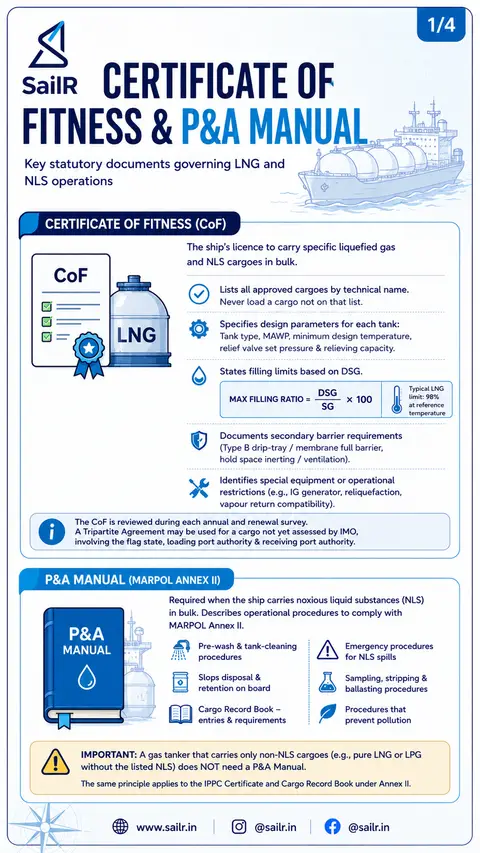
Slide 1 · 1/4
CERTIFICATE OF
FITNESS & P&A MANUAL
Key statutory documents governing LNG and
NLS operations
CERTIFICATE OF FITNESS (CoF)
CoF
LNG
The ship's licence to carry specific liquefied gas
and NLS cargoes in bulk.
Lists all approved cargoes by technical name.
Never load a cargo not on that list.
Specifies design parameters for each tank:
Tank type, MAWP, minimum design temperature,
relief valve set pressure & relieving capacity.
States filling limits based on DSG.
MAX FILLING RATIO = DSG / SG × 100
Typical LNG limit: 98% at reference temperature
Documents secondary barrier requirements
(Type B drip-tray / membrane full barrier,
hold space inerting / ventilation).
Identifies special equipment or operational restrictions (e.g., IG generator, reliquefaction, vapour return compatibility).
The CoF is reviewed during each annual and renewal survey.
A Tripartite Agreement may be used for a cargo not yet assessed by IMO, involving the flag state, loading port authority & receiving port authority.
P&A MANUAL (MARPOL ANNEX II)
P&A MANUAL
Required when the ship carries noxious liquid substances (NLS) in bulk. Describes operational procedures to comply with MARPOL Annex II.
Pre-wash & tank-cleaning procedures
Emergency procedures for NLS spills
Slops disposal & retention on board
Sampling, stripping & ballasting procedures
Cargo Record Book – entries & requirements
Procedures that prevent pollution
IMPORTANT: A gas tanker that carries only non-NLS cargoes (e.g., pure LNG or LPG without the listed NLS) does NOT need a P&A Manual.
The same principle applies to the IPPC Certificate and Cargo Record Book under Annex II.
Slide 2 · 2/4
PRE-LOADING PREPARATION
FOR LNG
Essential checks and preparations before LNG transfer
1
CARGO VERIFICATION
• Confirm LNG (methane) is on CoF
• Verify cargo composition
• Obtain SDS from shipper
2
LOADING PLAN
• Calculate filling limit (98% for LNG)
• Account for heel and ullage
• Determine available capacity
3
STABILITY & DRAFT CHECK
• Verify trim (stern trim preferred)
• Check under-keel clearance (UKC)
• Ensure compliance with load line
4
SHIP/SHORE SAFETY CHECKLIST
• Test ESD link and emergency release
• Confirm vapour return connection
• Access control & communication test
5
INERTING & DRYING
• Inert tank/hold spaces
• O₂ level below required limit (<5%)*
• Dew point below −45°C
• Prevent ice formation
*Refer to ship's Cargo Manual for exact O₂ operational limit.
CRITICAL LNG PRINCIPLE
RAPID COOLING CAUSES THERMAL SHOCK
Controlled cooldown is mandatory to protect tank structure.
KEY OBJECTIVES
Ensure safe operations
Prevent icing & thermal shock
Protect tank integrity
Prevent pollution & emissions
IMPORTANT
Do not proceed to cooldown or loading until all preparations are completed and verified.
Slide 3 · 3/4
LNG COOLDOWN &
CARGO TRANSFER
Controlled operations for safe and efficient LNG loading
BOG MANAGEMENT
To Engine
for Fuel
To Reliquefaction
Plant (if fitted)
To Mast Riser
(If permitted)
VAPOUR
(BOG)
TEMP.
SENSORS
LEVEL
GAUGE
LNG SPRAY
(COOLDOWN)
PRESSURE
MONITOR
LNG
KEY MONITORING DURING LOADING
PRESSURE
Keep below relief valve set
pressure (typ. 0.25–0.7 bar
for LNG)
LEVEL
Use radar/ultrasonic gauges
Avoid stratification
TEMPERATURE
Ensure uniform cooldown
within design limits
TRIM & STRESS
Adjust ballast to maintain
hull girder stresses within
permissible limits
1
COOLDOWN
Introduce LNG spray
into tank
Max temperature drop
rate ≤ 10°C per hour
Target tank temperature:
−130°C to −140°C
(uniform cooling)
2
LOW-RATE LOADING
Start loading at 10–20%
of maximum rate
Confirm stable cooldown
profile
Monitor BOG pressure
& tank conditions
3
FULL-RATE TRANSFER
Increase to full loading rate
Monitor and manage tank
pressure
Manage BOG: engine fuel /
reliquefaction / vent
Maintain trim and hull
stress within limits
4
TOP-OFF PHASE
Approaching 98% filling limit
Reduce loading rate
High level alarm & ESD
protection active
Prevent overfill at all times
5
VAPOUR RETURN
Displaced vapour returned
ashore or burned
Maintain slight positive
pressure to prevent
air ingress
OPERATION GOLDEN RULE
CONTROLLED COOLDOWN + MONITORING = SAFE LOADING
Follow Cargo Manual, IGC Code & SIGTTO Best Practices at all times.
Slide 4 · COMPLETION &
COMPLETION &
POST-LOADING SAFETY
Final steps to secure the cargo and prepare for departure
1
STOP TRANSFER &
DISCONNECT
Shut cargo valves
Blow-down loading arms
(Nitrogen / Cooldown & Drain)
Disconnect Emergency
Release Coupler (ERC)
Ensure all
loading arms
are safe and
depressurized
2
SECURE CARGO
SYSTEM
Close and secure manifold valves
Isolate vapour return line
Verify tank pressure is stable
Confirm all cargo vents
and systems secured
Maintain tank
pressure within
design limits
3
DOCUMENTATION
& RECORDS
Complete Bill of Lading
Record cargo transfer
details
Update Cargo Record
Book (if NLS)
Make entry in Deck Log
and C/O report
Accurate records ensure compliance
with IGC Code & MARPOL Annex II
(where applicable)
4
DEPARTURE
READINESS
Confirm hold space inerting /
ventilation normal
Ensure cargo system isolated
and secure
Verify moorings and fenders
ready for safe departure
Safety first
at every
step
KEY SAFETY REMINDERS
Follow Cargo
Manual, IGC Code
& SIGTTO Best
Practices
Monitor Tank
Temperature,
Pressure &
Levels
Maintain
Communication
with Terminal
at all times
Never bypass
alarms, interlocks
or safety
procedures
Manage BOG
responsibly –
engine / reliq.
/ vent
NEVER LOAD A CARGO NOT LISTED ON THE CoF
SAFETY • COMPLIANCE • PROTECTION OF LIFE & ENVIRONMENT
Drafted by SailR from our daily lessons. AI-drawn illustration. Simplified to explain the idea, not to scale. Last updated 19 Oct 2026.
Spotted a mistake?