The slides, written out
AI-drawn illustration. Simplified to explain the idea, not to scale.
Slide 1 · ELECTROMAGNETIC
ELECTROMAGNETIC
(EM) LOG
PRINCIPLE & APPLICATIONS
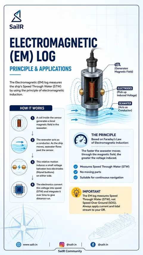
The Electromagnetic (EM) log measures
the ship's Speed Through Water (STW)
by using the principle of electromagnetic
induction.
HOW IT WORKS
1 A coil inside the sensor
generates a local
magnetic field in the
seawater.
2 The seawater acts as
a conductor. As the ship
moves, seawater flows
past the sensor.
3 This relative motion
induces a small voltage
between two electrodes
(Monel buttons)
on either side.
4 The electronics convert
this voltage into speed
(STW) and integrate it
over time to give
distance run.
COIL
(Generates
Magnetic Field)
ELECTRODES
(Pick up
Induced Voltage)
SEAWATER
(Acts as
Conductor)
THE PRINCIPLE
Based on Faraday's Law
of Electromagnetic Induction:
The faster the seawater moves
through the magnetic field, the
greater the voltage induced.
Measures Speed Through Water (STW)
No moving parts
Suitable for continuous navigation
IMPORTANT
The EM log measures Speed
Through Water (STW), not
Speed Over Ground (SOG).
Always apply current and tidal
stream to your DR.
| |
Slide 2 · ERRORS & PRACTICAL
ERRORS & PRACTICAL
CAUTIONS OF EM LOG
Every OOW must know the limitations of the EM log to avoid
navigational errors.
1 WATER MOTION EFFECT
(THE BIG ONE)
FOLLOWING
CURRENT
HEAD
CURRENT
EM log measures Speed Through Water
(STW), not Speed Over Ground (SOG).
Following current → log underreads.
Head current → log overreads.
Always apply current & tidal stream
to your DR.
2 SEA STATE & VESSEL MOTION
Heavy seas, pitching,
heaving and turbulent
water flow around the
sensor may introduce
measurement errors.
The magnitude and
direction depend on
vessel motion, sensor
location and hull
characteristics.
3 LOW SPEED & ASTERN
INACCURACY
At very low speed, the induced signal is
very small and can be affected by noise.
During astern movement, propeller wash
and turbulent flow around the sensor
reduce accuracy. Do not rely on it for
docking or precise sternway.
4 TRIM & LIST
Heavy trim by stern
or significant list can
alter water flow past
the sensor, causing
small measurement
errors.
5 CALIBRATION
ERRORS
Calibration is carried out
using a measured distance
or approved reference
method. Calculation of
percentage error should
follow the manufacturer's
procedure or exam
requirement.
6 AIR BUBBLES & FOULING
Air bubbles drawn along
the hull or marine growth
on the sensor face can
disrupt water flow and
attenuate the signal.
Clean the sensor at
regular drydock.
OPERATIONAL TIP
Regularly compare EM log with GPS SOG.
Monitor sudden changes in log behavior.
Understand your log's limitations.
Good seamanship + correct application
= accurate navigation.
Slide 3 · JANUS
JANUS
CONFIGURATION
IN DOPPLER SPEED LOGS
The Janus configuration uses forward and aft inclined transducer pairs to eliminate the effects of vessel motion (pitch, heave and trim) and provide accurate longitudinal speed.
HOW IT WORKS
1 DUAL BEAMS
One transducer beams forward and the other beams aft at the same inclination angle.
2 DOPPLER SHIFT
Each returning echo is Doppler-shifted by the combination of the ship's horizontal speed and vessel motion.
3 MOTION CANCELLATION
The processor uses Doppler geometry to separate the longitudinal speed from pitch, heave and trim components.
4 ACCURATE SPEED
The result is a clean, accurate reading of the ship's Speed Through Water (STW) in the longitudinal direction.
JANUS PRINCIPLE (LONGITUDINAL)
FORWARD BEAM
Transmits forward at an angle
AFT BEAM
Transmits aft at the same angle
Both beams measure Doppler shift simultaneously.
Processor combines both measurements to cancel vessel motion effects and calculate accurate longitudinal speed.
Adding a second pair of transducers athwartships (port & starboard) provides the ship's transverse speed.
RESULT:
Longitudinal speed (fore & aft)
Transverse speed (port & starboard)
USED FOR
Docking & undocking
Harbour approaches
Dynamic positioning support
Berthing alongside
DUAL-AXIS (DOCKING) CONFIGURATION
FORWARD BEAM
PORT BEAM
STARBOARD BEAM
AFT BEAM
Slide 4 · EM LOG vs
EM LOG vs
DOPPLER LOG
KEY DIFFERENCES AT A GLANCE
Both systems measure Speed Through Water (STW) but use different principles and are suited to different operational needs.
EM LOG
Electromagnetic Induction
DOPPLER LOG
Doppler Effect (Acoustic)
FEATURE | EM LOG | DOPPLER LOG
PRINCIPLE | Electromagnetic induction (Faraday's Law) | Doppler shift of acoustic waves
MEASURES | Speed Through Water (STW) only | STW and, in bottom track mode, velocity over seabed
MOVING PARTS | No moving parts | No moving parts (solid-state transducers)
LOW SPEED PERFORMANCE | Less accurate at very low speeds | Better accuracy at low speeds
ASTERN OPERATION | Unreliable in sternway due to disturbed flow | More reliable in astern, less affected by prop wash
MOTION COMPENSATION | Affected by pitch, heave, trim and turbulence | Janus configuration reduces motion errors
DOCKING USE | Limited usefulness | Dual-axis logs provide fore-aft & port-starboard speeds for docking
CURRENT MEASUREMENT | Cannot measure current directly | Bottom track mode can show set & drift (if depth & bottom conditions permit)
MAINTENANCE | Clean sensor face, ensure no fouling or air bubbles | Keep transducer face clean; check mounting and alignment
CALIBRATION | Via measured mile or approved method | Calibration per manufacturer using test run / reference method
KEY TAKEAWAYS
EM log uses Faraday's Law.
Measures Speed Through Water only.
Doppler log uses acoustic Doppler shift.
Janus configuration improves motion compensation.
Dual-axis Doppler systems excel during docking.
| |
Drafted by SailR from our daily lessons. AI-drawn illustration. Simplified to explain the idea, not to scale. Last updated 19 Oct 2026.
Spotted a mistake?