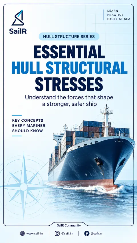
The slides, written out
AI-drawn illustration. Simplified to explain the idea, not to scale.
Slide 1 · LEARN
LEARN
PRACTICE
EXCEL AT SEA
HULL STRUCTURE SERIES
ESSENTIAL
HULL STRUCTURAL
STRESSES
Understand the forces that shape
a stronger, safer ship
KEY CONCEPTS
EVERY MARINER
SHOULD KNOW
Slide 2 · Hull Structure Series
Hull Structure Series
Essential Hull Structural Stresses
RACKING STRESSES
Transverse distortion of the hull
When a ship rolls in a seaway or is subjected to beam waves,
unequal transverse loading can distort the hull cross section.
The normally rectangular cross section tends to deform
toward a parallelogram. This distortion is called racking.
Normal Section
Under Racking
Higher
pressure
on this side
Lower
pressure
on this side
Rectangular cross section
Distorted to a parallelogram
What Resists Racking?
Transverse bulkheads
Transverse framing
Deep web frames
Associated structural members
Key Survey Point
Racking stresses are particularly
significant at the corners of the box
section and around structural
discontinuities.
Pay special attention to:
Corner brackets
Beam knees
Structural connections
Areas around openings
EXAM KEYWORD
Racking = Transverse distortion
of hull cross section
LEARN
PRACTICE
EXCEL AT SEA
Slide 3 · Hull Structure Series
Hull Structure Series
Essential Hull Structural Stresses
PANTING & POUNDING
Two important end region stresses
PANTING
POUNDING
Rhythmic in-and-out movement
Sudden impact loading
Fluctuating water pressure causes shell plating at the bow and stern to flex in and out. It is particularly severe at the forward end, especially when the ship is making headway into a seaway.
When the bow pitches clear of the water and then comes down heavily onto the sea, a severe shock load is produced. Pounding is primarily a forward-end loading problem, particularly in the forward bottom region, and the structure is strengthened accordingly.
Panting action at forward end
Pounding (slamming) at forward end
Resisted by
Structural measures
Panting beams
Panting stringers
Breast hooks
Deep floors
Closer frame spacing
Increased structural strength
Increased plate thickness where required
REMEMBER
Panting = Repeated flexing
Pounding = Impact / Slamming
LEARN PRACTICE EXCEL AT SEA
Slide 4 · Hull Structure Series
Hull Structure Series
Essential Hull Structural Stresses
FLOOR PLATE
A structural member of the double bottom
A floor plate is a structural transverse plate forming part of the double-bottom structure. It supports the bottom structure and inner bottom and connects with the longitudinal girders.
Main Functions
Common Arrangements
Supports the bottom structure
Supports the inner bottom (tank top)
Connects with longitudinal girders
Provides transverse strength and rigidity
Solid Plate Floor
Continuous transverse structural plate.
Bracket Floor
Transverse bracketed structural arrangement, depending on the double-bottom framing system.
Typical Double-Bottom Section
Inner Bottom (Tank Top)
Floor Plate (transverse)
EXAM SKETCH TIP
Show a section with: outer bottom shell, inner bottom, a solid floor plate spanning between them, with a vertical web and stiffeners.
Outer Bottom Shell
Longitudinal Girders
EXAM KEYWORD
Floor plate = Transverse structural member of the double bottom
LEARN PRACTICE EXCEL AT SEA
Slide 5 · Hull Structure Series
Hull Structure Series
Essential Hull Structural Stresses
SHEAR STRAKE
Uppermost strake of side shell plating
The shear strake is the uppermost continuous strake of side shell plating, adjoining the strength deck. It forms an important part of the longitudinal strength of the hull.
Why is it Important?
• Hull-girder bending produces high longitudinal stresses toward the extreme top and bottom of the hull girder.
• The shear strake therefore carries significant longitudinal loads, particularly in the strength-deck region.
Works With
The shear strake works together with the stringer plate.
• Stringer plate = outboard strake of deck plating.
• They are joined at the deck edge, which is a highly stressed zone on the vessel.
Survey Attention
• The deck-edge connection between shear strake and stringer plate is a significant structural detail.
• Stress concentrations can occur in this region, so it receives special attention during surveys.
Material Consideration
Depending on:
• Design temperature
• Structural location
• Material thickness
• Applicable classification requirements
the steel in critical hull structural regions such as the shear strake may require specified impact toughness.
Deck
Stringer Plate (outboard deck strake)
Shear Strake (uppermost side shell strake)
Side Shell Plating
EXAM KEYWORD
Shear strake = Uppermost side shell strake adjoining the strength deck.
LEARN PRACTICE EXCEL AT SEA
Drafted by SailR from our daily lessons. AI-drawn illustration. Simplified to explain the idea, not to scale. Last updated 19 Oct 2026.
Spotted a mistake?