Fatigue Cracking in Marine Diesel Engine Bedplate Transverse Girders: Causes and Prevention
- times asked
- 41
- times asked
- questions
- 6
- questions
- last asked
- 2026
- last asked
Fatigue cracks can develop under repeated stress, even when individual stress levels are below the material’s static strength. Learn the causes of fatigue cracking, the effect of material and design defects, and the preventive measures used on marine diesel engine bedplates.
The slides, written out
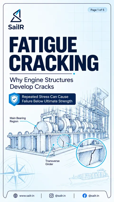
AI-drawn illustration. Simplified to explain the idea, not to scale.
Slide 1 · Fatigue cracking develops when an engineering component experiences repeated or fluctua…
Fatigue cracking develops when an engineering component experiences repeated or fluctuating stress. A crack can grow progressively over many stress cycles, even when the stress remains below the material’s ultimate strength. Understanding the causes helps engineers reduce cracking risks in marine engine structures.
Slide 2 · Fatigue cracking is influenced by cyclic stress, the number and frequency of loading cy…
Fatigue cracking is influenced by cyclic stress, the number and frequency of loading cycles, stress concentrations, material condition and excessive static loading. Higher cyclic stress generally reduces the number of cycles a component can withstand. Notches, sharp section changes, surface damage and material defects can initiate cracks, while excessive preload can increase the total working stress.
Slide 3 · Material defects such as inclusions, porosity and pre-existing cracks can provide locat…
Material defects such as inclusions, porosity and pre-existing cracks can provide locations for fatigue crack initiation. Design defects, including sharp corners, abrupt section changes and poorly arranged holes, create local stress concentrations. Surface damage and defective repairs can also shorten fatigue life. A visible surface crack may extend internally, making suitable non-destructive examination important.
Slide 4 · Fatigue cracking in marine diesel engine bedplate transverse girders can be associated…
Fatigue cracking in marine diesel engine bedplate transverse girders can be associated with abnormal loading, inadequate restraint, alignment problems, stress concentrations and manufacturing or repair defects. Correct engine support, appropriate tie-bolt tension and attention to bearing support help control structural movement and abnormal loading. Susceptible regions include bearing-girder areas, welds, holes and geometric discontinuities.
Slide 5 · Fatigue cracking can be minimised by maintaining correct engine support, alignment and…
Fatigue cracking can be minimised by maintaining correct engine support, alignment and loading, controlling stress concentrations, and maintaining high manufacturing and repair quality. Systematic inspection should focus on susceptible bedplate regions. Suitable non-destructive examination should be used when visual inspection cannot establish the extent of a suspected crack, and findings should be compared over time to identify changes.
What it is
Fatigue cracking is progressive structural damage caused by repeated or fluctuating stress. A metal component can develop fatigue cracks even when its nominal stress remains below its static yield strength. Damage accumulates through repeated loading, and a crack can grow until the remaining section can no longer withstand the applied load. The process involves crack initiation, crack propagation and eventual fracture. (Fine and Chung, “Fatigue Failure in Metals,” ASM Handbook, Volume 19, pp. 63–72)
In a marine diesel engine, the bedplate supports the crankshaft main bearings and forms part of the engine's structural framework. Large marine engines commonly use longitudinal girders and transverse girders with bearing supports. These structures must withstand the forces transmitted through the crankshaft and its bearings during operation. (MAN B&W, “ME Engine Description,” section “Bedplate and Main Bearing”)
Why it matters
The fatigue life of a component depends on its cyclic loading and material condition. Higher cyclic stress generally reduces the number of cycles that a component can withstand before fatigue failure. Mean stress also affects fatigue life, so an excessive preload can change the stress experienced during normal operation. The assessment must consider the actual loading conditions rather than relying on static strength alone. (Mitchell, “Fundamentals of Modern Fatigue Analysis for Design,” ASM Handbook, Volume 19, pp. 227–249)
Stress concentrations make particular locations more vulnerable. Scratches, sharp changes in cross-section, pits and inclusions can act as fatigue crack initiation sites. Weld defects and manufacturing irregularities can also provide locations from which cracks develop. Once a crack has started, continued cyclic loading can allow it to propagate through the component. (Fine and Chung, “Fatigue Failure in Metals,” ASM Handbook, Volume 19, pp. 63–72)
How it works on board
Bedplate transverse girders require attention because they support the main-bearing regions and form part of the engine's load-carrying structure. Cracking can occur at the junctions between transverse and longitudinal girders, beneath bearing pockets and around other structural discontinuities. Manufacturing defects, uneven loading, engine overloading, loose tie-bolts and loose holding-down bolts are recognised possible causes of bedplate cracking. (Maritime Knowledge, “Engine Structure – Introduction,” section “Main Propulsion System”)
Engine support and restraint must be maintained in accordance with the engine manufacturer's instructions. Tie-bolts should be checked and adjusted using the specified tightening pressures and sequence. The correct procedure depends on the engine design and its arrangements. A universal tightening sequence or tension value should not be assumed. (MarineDiesels.info, “The Two Stroke Crosshead Diesel Engine Tie Bolts”)
Abnormal loading and alignment concerns should be investigated when they are identified. Stress concentrations around holes, welds and changes in section also deserve attention during inspection. When a crack is suspected, visual appearance alone may not establish its full extent. Appropriate non-destructive examination can help determine the condition of the affected area, with the method selected according to the material, component and suspected defect.
The rules
Follow the engine manufacturer's maintenance instructions for tie-bolt tension, holding-down arrangements, alignment checks and repairs. The correct procedures are engine-specific. (MarineDiesels.info, “The Two Stroke Crosshead Diesel Engine Tie Bolts”)
Inspect susceptible bedplate regions, including transverse-girder welds and areas beneath bearing pockets, according to the applicable maintenance instructions and inspection plan. (Maritime Knowledge, “Engine Structure – Introduction,” section “Main Propulsion System”)
Investigate abnormal loading, loose restraint or suspected structural damage rather than allowing the condition to continue without assessment. (Maritime Knowledge, “Engine Structure – Introduction,” section “Main Propulsion System”)
Use suitable non-destructive examination when the extent of suspected cracking cannot be established by visual inspection. Select the method and acceptance criteria for the specific component and defect.
Record inspection findings and compare them over time when monitoring crack progression. Repair decisions should be based on the actual condition and the applicable manufacturer's or repair authority's requirements.
Common mistakes
One common mistake is to assume that fatigue cracking requires stress above the material's static strength. Fatigue damage can develop under repeated loading at much lower nominal stress levels. The relevant loading history and local stress conditions must therefore be considered. (Fine and Chung, “Fatigue Failure in Metals,” ASM Handbook, Volume 19, pp. 63–72)
Another mistake is to overlook local stress concentrations. A component may have an acceptable nominal stress while a notch, sharp corner, surface defect or inclusion creates a more severe local condition. Inspection and design review should consider these locations, especially when a crack has already been suspected. (Fine and Chung, “Fatigue Failure in Metals,” ASM Handbook, Volume 19, pp. 63–72)
A further mistake is to treat every marine diesel engine as having the same tie-bolt arrangement or maintenance procedure. Engine designs differ, and the correct tightening pressures, sequence and related checks must come from the applicable instructions. Overtightening should not be used as a substitute for correct adjustment. (MarineDiesels.info, “The Two Stroke Crosshead Diesel Engine Tie Bolts”)
Publication note: The article uses the verified technical principles and the marine-engine claims retained in the audit. The sources include engineering handbooks and specialist marine-engine references rather than a single universal statutory rule. Before publication, check the linked technical documents and use the specific engine manufacturer's documentation for any operational procedure or acceptance limit.
In exams
Asked 41 times across 6 different questions, most recently in 2026. Asked most in MEO Class 2 (33), MEO Class 4 (8).
Sources
- Fine, M. E., and Chung, Y.-W. “Fatigue Failure in Metals.” ASM Handbook, Volume 19: Fatigue and Fracture, pp. 63–72.
- Mitchell, M. R. “Fundamentals of Modern Fatigue Analysis for Design.” ASM Handbook, Volume 19: Fatigue and Fracture, pp. 227–249.
- MAN B&W. “ME Engine Description,” Project Guide, section “Bedplate and Main Bearing.”
- Maritime Knowledge. “Engine Structure – Introduction,” section “Main Propulsion System.”
- MarineDiesels.info. “The Two Stroke Crosshead Diesel Engine Tie Bolts.”
Drafted by SailR from the regulations cited. AI-drawn illustration. Simplified to explain the idea, not to scale. Last updated 1 Nov 2026.
Spotted a mistake?