The slides, written out
AI-drawn illustration. Simplified to explain the idea, not to scale.
Slide 1 · FATIGUE
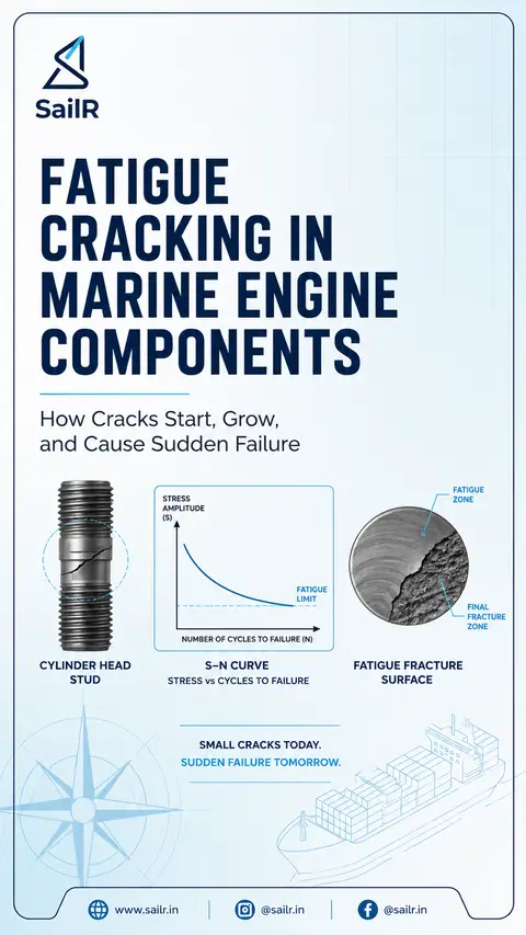
FATIGUE
CRACKING IN
MARINE ENGINE
COMPONENTS
How Cracks Start, Grow,
and Cause Sudden Failure
STRESS
AMPLITUDE
(S)
FATIGUE
LIMIT
NUMBER OF CYCLES TO FAILURE (N)
FATIGUE
ZONE
FINAL
FRACTURE
ZONE
CYLINDER HEAD
STUD
S–N CURVE
STRESS vs CYCLES TO FAILURE
FATIGUE FRACTURE
SURFACE
SMALL CRACKS TODAY.
SUDDEN FAILURE TOMORROW.
Slide 2 · FROM MICRO-CRACK
FROM MICRO-CRACK
TO FAILURE
How fatigue cracks develop under
repeated cyclic loading
1 CRACK
INITIATION
2 CRACK
PROPAGATION
3 FINAL
FRACTURE
• Starts at a point of
stress concentration
• Surface scratches,
tool marks, sharp
edges
• Thread roots,
poor fillet radii
• Inclusions, porosity
or existing flaws
• Each load cycle
advances the crack
a tiny amount
• Crack grows
gradually
• Fracture surfaces
show beach marks
and microscopic
striations
• Remaining cross-
section is too small
to carry the load
• Sudden, rapid
overload failure
• Rough, crystalline
fracture surface
WHAT THE FRACTURE SURFACE TELLS YOU
Large fatigue zone
+ small final fracture
Small fatigue zone
+ large final fracture
→ Low-stress, high-cycle fatigue
(e.g., misaligned coupling,
millions of cycles)
→ High-stress, low-cycle fatigue
(e.g., pressure vessel cycle,
starting air receiver)
Slide 3 · WHY CYLINDER
WHY CYLINDER
HEAD STUDS FAIL
Poor maintenance practices accelerate
fatigue cracking
1
SURFACE
DAMAGE
Scratches, nicks and
tool marks create stress
concentrations.
Thread damage
(cross-threading,
burrs) acts as a crack
initiation site.
Local stress can exceed
fatigue limit, causing
early crack initiation.
2
CORROSION
FATIGUE
Cooling water leaks
or aggressive
atmosphere cause
corrosion pits.
Pits become crack
initiation sites under
cyclic loading.
Crack opening/closing
prevents protective
film formation and
accelerates damage.
3
INCORRECT
PRELOAD
Over-tightening: may raise mean
stress; harmful if yielding or
thread damage occurs.
Uneven tightening: introduces
bending stress, worst at thread
run-out.
Under-tightening: joint
separates under gas pressure,
increasing stress amplitude
and accelerating fatigue.
4
MISSED REPLACEMENT
INTERVALS
Head studs are designed
for a finite running life
(number of cycles).
Failure to log running hours
and replace on schedule
leads to operation beyond
safe fatigue life.
Fatigue damage accumulates
silently until sudden failure.
Good maintenance, correct tightening and timely replacement
greatly extend stud life and prevent catastrophic failure.
Slide 4 · ENGINE OVERLOAD & FATIGUE LIFE
ENGINE OVERLOAD & FATIGUE LIFE
Overload conditions increase stress and reduce fatigue life
1
INCREASED CYLINDER PRESSURE
• Overload (high BMEP, excessive scavenge pressure, poor timing) raises peak firing pressure.
• Higher peak tensile load each cycle increases stress amplitude.
• According to the S–N curve, higher stress = fewer cycles to failure.
2
ELEVATED TEMPERATURE
• Overload increases average temperature in the cylinder and components.
• Higher temperature reduces material fatigue strength.
• Combination of high mean stress and temperature accelerates fatigue damage.
3
VIBRATION EFFECTS (TORSIONAL & RESONANCE)
• Running near critical speed causes torsional vibration.
• Dynamic stresses are added to the static load.
• Sustained vibration increases fatigue crack growth rate and risk of sudden failure.
OVERLOAD (HIGHER ENGINE LOAD)
IMPACT ON STUDS
PRESSURE ↑ Higher peak tensile load
TEMPERATURE ↑ Lower fatigue strength
STRESS ↑ Higher mean and dynamic stress
FATIGUE LIFE ↓ Fewer cycles to failure
KEY TAKEAWAY
Fatigue failures rarely occur without warning. Control engine load, avoid resonance, maintain correct preload, prevent corrosion, and follow replacement schedules to protect critical components.
Drafted by SailR from our daily lessons. AI-drawn illustration. Simplified to explain the idea, not to scale. Last updated 19 Oct 2026.
Spotted a mistake?