The slides, written out
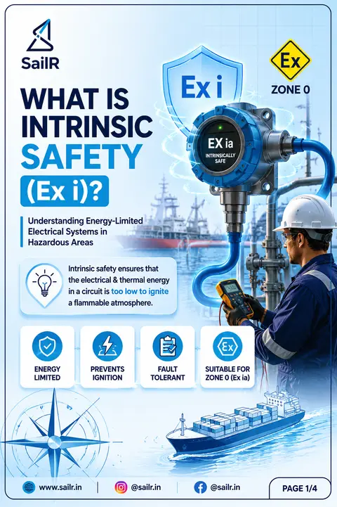
AI-drawn illustration. Simplified to explain the idea, not to scale.
Slide 1 · WHAT IS
WHAT IS
INTRINSIC
SAFETY
(Ex i)?
Understanding Energy-Limited
Electrical Systems in
Hazardous Areas
Intrinsic safety ensures that
the electrical & thermal energy
in a circuit is too low to ignite
a flammable atmosphere.
ENERGY
LIMITED
PREVENTS
IGNITION
FAULT
TOLERANT
SUITABLE FOR
ZONE 0 (Ex ia)
PAGE 1/4
Ex i
Ex
ZONE 0
EX ia
INTRINSICALLY
SAFE
Slide 2 · THE PRINCIPLE
THE PRINCIPLE
BEHIND
Ex i PROTECTION
How Intrinsic Safety Works
NON-HAZARDOUS AREA
ELECTRICAL
SOURCE
SAFETY BARRIER / ISOLATOR
LIMITS VOLTAGE
& CURRENT TO
A SAFE LEVEL
HAZARDOUS AREA
FIELD DEVICE
(Ex i EQUIPMENT)
ENERGY IS LIMITED BY
DESIGN
VOLTAGE
LIMITED
Maximum voltage
kept below ignition
levels
CURRENT
LIMITED
Current restricted
to prevent excessive
energy release
TEMPERATURE
CONTROLLED
Thermal energy
kept below ignition
temperature
FAULT
TOLERANT
Remains safe even
under specified
fault conditions
Instead of containing an explosion,
intrinsic safety prevents ignition
by ensuring that any spark or hot surface
cannot ignite a flammable gas or vapour
mixture.
PAGE 2/4
Slide 3 · LIVE WORK ON
LIVE WORK ON
Ex i CIRCUITS
Ex i
Can Live Maintenance Be Performed?
ALLOWED (Under Approved Procedures)
TESTING
Checking signals and instrument performance while energized.
CALIBRATION
Calibrating field devices as per manufacturer instructions.
FAULT FINDING
Locating and diagnosing faults without interrupting operations.
SIGNAL VERIFICATION
Measuring and verifying signals within Ex i parameters.
NOT ALLOWED (Will Compromise Safety)
UNAUTHORIZED MODIFICATIONS
Making changes to the circuit or equipment.
NON-CERTIFIED COMPONENTS
Using parts or materials not approved for Ex i applications.
ALTERING CABLE PARAMETERS
Changing cable type, length or routing in ways not certified.
BREAKING CERTIFIED INTEGRITY
Damaging, bypassing or compromising any part of the Ex i system.
KEY TAKEAWAY
Intrinsically safe circuits are designed to allow certain energized maintenance activities, provided the certified Ex i installation remains intact and company procedures, hazardous-area requirements and manufacturer instructions are followed at all times.
REMEMBER
When in doubt, isolate and de-energize before you work. Follow Lock-Out / Tag-Out and permit procedures.
LOCKOUT TAG OUT
PAGE 3/4
Slide 4 · WHERE YOU'LL FIND
WHERE YOU'LL FIND
Ex i EQUIPMENT
ON BOARD
Common Shipboard Applications
Used in hazardous areas where any spark or hot surface must be prevented from igniting a flammable atmosphere.
FIXED GAS DETECTION SYSTEMS
Sensors in cargo pump rooms, compressor rooms, tank tops and other hazardous areas.
CARGO TANK GAUGING SYSTEMS
Radar, servo and capacitance level gauges powered through Ex i safety barriers.
TEMPERATURE MONITORING
RTDs and temperature probes in cargo tanks, slop tanks and other hazardous spaces.
HAZARDOUS AREA COMMUNICATIONS
Telephones, public address speakers and sounders installed in hazardous locations.
PORTABLE EQUIPMENT
Intrinsically safe two-way radios and torches for use in pump rooms, cargo areas and tank spaces.
GOLDEN RULES FOR Ex i INSTALLATIONS
BLUE IDENTIFICATION
Blue cables and terminals indicate Ex i circuits.
SEPARATE ROUTING
Route separately from power cables to prevent induction of dangerous voltages.
CERTIFIED JUNCTION BOXES
Use certified Ex i junction boxes and approved components only.
MAINTAIN INTEGRITY
Never modify or replace with non-certified parts. Preserve the entire certified system.
REMEMBER
The safety of an Ex i system depends on maintaining the complete certified combination of safety barrier, cable, field device and installation.
PAGE 4/4
Drafted by SailR from our daily lessons. AI-drawn illustration. Simplified to explain the idea, not to scale. Last updated 19 Oct 2026.
Spotted a mistake?