The slides, written out
AI-drawn illustration. Simplified to explain the idea, not to scale.
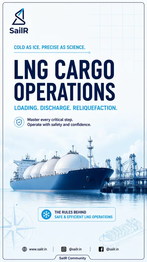
Slide 1 · COLD AS ICE
COLD AS ICE. PRECISE AS SCIENCE.
LNG CARGO
OPERATIONS
LOADING. DISCHARGE. RELIQUEFACTION.
Master every critical step.
Operate with safety and confidence.
THE RULES BEHIND
SAFE & EFFICIENT LNG OPERATIONS
Slide 2 · SLIDE 1 OF 4
LOADING LNG
Before LNG Enters the Tanks
01
SHIP SHORE SAFETY FIRST
Before cargo transfer or cooldown begins:
Test the Ship Shore Link (SSL)
Test the Emergency Shutdown (ESD) system
Confirm ship and terminal ESD communication
Verify cargo transfer systems are ready
SIGTTO recommends SSL testing as part of the pre-transfer test, including verification of communication in both directions.
Source: SIGTTO – ESD Systems Guide (2021)
02
CONTROLLED COOLDOWN
Cooldown must follow the ship's approved cooldown procedure.
MONITOR:
Tank temperature
Piping temperature
Temperature gradients
Cargo containment limitations
The IGC Code recognises transient thermal loads during cooldown and requires protection of the hull from temperatures below allowable limits.
Source: IGC Code – 2016, Chapter 18.5 & 18.6
03
CONTROLLED LOADING
LNG enters through the liquid cargo system while displaced vapour is managed through the approved vapour return/handling arrangement.
LNG IN
Tank filling sequence must follow the vessel's approved loading plan considering:
STABILITY | TRIM | STRENGTH | FILLING LIMITS | SLOSHING
KEY TAKEAWAY:
Cooldown is not simply "make the tank cold."
Control the temperature and temperature gradients.
| |
Slide 3 · SLIDE 2 OF 4
DISCHARGING LNG
When Liquid Leaves, Vapour Must Replace It
As LNG is pumped from the cargo tanks, the removed liquid volume must be replaced by vapour to maintain acceptable tank pressure.
01
NORMAL DISCHARGE
Where shore vapour return is available:
VAPOUR RETURN FROM SHORE
SHORE VAPOUR RETURN
CARGO TANK VAPOUR SPACE
Shore returns vapour to the ship to replace the liquid discharged and maintain pressure.
LNG OUT
02
NO SHORE VAPOUR RETURN
Where shore cannot supply return vapour:
LNG is vaporised and the resulting gas is supplied to the cargo tank vapour space.
SHIP VAPORISER (WHERE FITTED)
CARGO TANK VAPOUR SPACE
PURPOSE:
Replace displaced volume and support tank pressure control.
03
FOLLOW THE SHIP-SPECIFIC SEQUENCE
Discharge sequence is NOT prescribed universally by the IGC Code.
Sequence must follow the vessel's approved cargo operating/loading manual.
Based on longitudinal strength, trim, stability and cargo system limitations.
Typical four-tank ships may use different orders depending on design and condition.
Never change sequence without approval.
FACTORS CONSIDERED
STABILITY
TRIM
LONGITUDINAL STRENGTH
CARGO SYSTEM LIMITATIONS
KEY TAKEAWAY:
Liquid out must be matched by vapour in – pressure control is the priority.
Slide 4 · SLIDE 3 OF 4
LOW LEVEL & FINAL DISCHARGE
The Last Metres Need the Most Attention
Final discharge and low-level operations must always follow the vessel's approved cargo operating procedures.
01
LOW LEVEL PUMPING
Do NOT apply a universal "2 metre rule."
The minimum operating level depends on the cargo pump and vessel-specific system.
FOLLOW THE APPROVED PROCEDURE FOR:
Minimum level
Pump operation
Recirculation (if required)
Stripping procedure
DEEPWELL PUMP
Minimum operating level – vessel specific
02
IF DISCHARGE IS INTERRUPTED
Where the vessel's approved procedure permits:
RECIRCULATE TO TANK
FROM PUMP
Maintain suitable pump conditions
Recirculate LNG within tanks
Resume discharge when ready
Never stop or start pumps contrary to the approved procedure.
Do not risk losing suction or damaging the pump.
03
DRAINING & NITROGEN PURGING
Before disconnecting cargo transfer equipment:
Drain remaining LNG from the liquid system as required.
Use nitrogen pressure from shore where required.
Purge the system with nitrogen.
Confirm hydrocarbon concentration is below the required limit before disconnection.
NITROGEN FROM SHORE
N2
TO TANK (VAPOUR LINE)
LIQUID LINE
DRAIN TO TANK (AS REQUIRED)
Follow the approved ship/terminal procedure for safe manifold draining, purging and disconnection.
KEY TAKEAWAY:
Final discharge is a procedure-driven operation.
Follow the approved limits and never rush the last step.
Slide 5 · SLIDE 4 OF 4
RELIQUEFACTION
Turning BOG Back Into Liquid
LIQUEFACTION
Gas → Liquid
Liquefaction occurs by bringing the substance into the liquid region of its phase diagram through cooling and/or compression.
For methane:
Critical temperature ≈ 190.56 K = −82.6°C
RELIQUEFACTION is the process of converting cargo vapour generated from the transported LNG back into liquid and returning it to the cargo tanks.
IGC CODE RECOGNISED SYSTEMS
01 DIRECT SYSTEM
Cargo vapour is compressed, condensed and returned to the tanks.
CARGO VAPOUR (BOG)
COMPRESSOR
CONDENSER
LNG RETURN TO TANK
02 INDIRECT SYSTEM
Cargo vapour is cooled or condensed by refrigerant without compression.
CARGO VAPOUR (BOG)
REFRIGERANT (HEAT EXCHANGER)
LIQUID LNG
LNG RETURN TO TANK
No cargo-vapour compression in the defining step.
03 COMBINED SYSTEM (IGC CODE TERM)
Cargo vapour is compressed and condensed in a cargo/refrigerant heat exchanger and returned to the tanks.
CARGO VAPOUR (BOG)
COMPRESSOR
CARGO / REFRIGERANT HEAT EXCHANGER
LIQUID LNG
LNG RETURN TO TANK
The IGC Code calls this a "COMBINED SYSTEM", not "cascade system".
ORAL EXAM TRIGGER – QUICK RECALL
DIRECT = Compress + Condense
INDIRECT = Refrigerate without cargo compression
COMBINED = Compress + Condense in cargo/refrigerant heat exchanger
Reliquefaction is one of the methods recognised by the IGC Code for cargo pressure and temperature control.
REFERENCE:
• IGC Code – Chapter 7 (Cargo Pressure/Temperature Control)
• IGC Code – Chapter 17 & 19 (May preclude or specify particular systems)
Drafted by SailR from our daily lessons. AI-drawn illustration. Simplified to explain the idea, not to scale. Last updated 19 Oct 2026.
Spotted a mistake?