Marine Two-Stroke SCR Systems: HPSCR vs LPSCR, Static Mixers and Tier III NOx Control
Selective Catalytic Reduction (SCR) is an exhaust after-treatment method used to reduce nitrogen oxide emissions from applicable marine engines. Understand how HPSCR and LPSCR differ, how reductant mixing works, and which operating limits must be followed for compliance.
The slides, written out
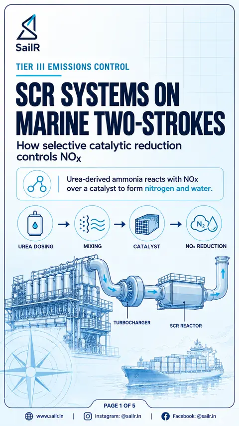
AI-drawn illustration. Simplified to explain the idea, not to scale.
Slide 1 · Selective Catalytic Reduction (SCR) is an exhaust after-treatment method used to reduce…
Selective Catalytic Reduction (SCR) is an exhaust after-treatment method used to reduce nitrogen oxide emissions from applicable marine engines. In the catalytic reaction, ammonia reacts with NOx to form nitrogen and water. A urea-water solution can supply the ammonia needed for the reaction. The system design must match the engine and its approved SCR specification.
Slide 2 · High-Pressure SCR (HPSCR) places the SCR reactor upstream of the turbocharger
High-Pressure SCR (HPSCR) places the SCR reactor upstream of the turbocharger. Low-Pressure SCR (LPSCR) places the reactor downstream of the turbocharger. The upstream arrangement receives exhaust before it passes through the turbine, while the downstream arrangement receives exhaust after turbine expansion. These arrangements have different pressure and temperature conditions, so the system design must account for the applicable operating limits and pressure loss.
Slide 3 · SCR systems use reductant injection and mixing arrangements to distribute ammonia throu…
SCR systems use reductant injection and mixing arrangements to distribute ammonia through the exhaust gas before it reaches the catalyst. A static mixer is a fixed device that can promote mixing. Uniform reductant distribution supports effective NOx conversion and helps minimise ammonia slip. The injection and mixing arrangement must follow the approved system design; no single mixer geometry or duct sequence applies universally to every installation.
Slide 4 · The position of the SCR reactor relative to the turbocharger determines the exhaust con…
The position of the SCR reactor relative to the turbocharger determines the exhaust conditions entering the reactor. An upstream reactor receives exhaust before the turbine, while a downstream reactor receives exhaust after expansion. Reactor pressure loss must be considered in the complete exhaust-system design because it can affect engine and turbocharger performance. Exhaust temperature must also remain within the limits specified for the approved SCR installation.
Slide 5 · SCR operating conditions must follow the approved system specification
SCR operating conditions must follow the approved system specification. The specified temperature limits, reductant requirements, pressure-loss limits, fuel compatibility conditions and control strategy must be respected. Space velocity relates exhaust-gas volumetric flow to catalyst volume and is a parameter in SCR design. Measures to control reductant slip form part of system design. SCR is one recognised method of achieving MARPOL Annex VI Tier III NOx compliance for applicable marine engines, subject to the relevant certification and verification requirements.
What it is
Selective Catalytic Reduction (SCR) reduces nitrogen oxide emissions by treating engine exhaust with a reductant in the presence of a catalyst. For applicable marine engines, SCR is one of the recognised technologies used to meet the NOx emission limits associated with MARPOL Annex VI Tier III. The system must be designed and verified in accordance with the applicable regulatory requirements. (MARPOL Annex VI, Regulation 13; IMO Resolution MEPC.399(83), Annex, §§1–2)
The reductant used in a marine SCR system can be supplied as a urea-water solution. When injected into sufficiently hot exhaust, the urea decomposes and hydrolyses to produce ammonia. The ammonia then reacts with NOx over the catalyst to form nitrogen and water. The exact operating conditions depend on the approved engine and SCR system configuration. (Wärtsilä, Selective Catalytic Reduction (SCR); IMO Resolution MEPC.399(83), Annex, §3.2)
Why it matters
SCR performance depends on the relationship between the reductant, the catalyst and the exhaust conditions. The system must provide suitable conditions for the catalytic reaction while controlling the amount of unreacted reductant leaving the reactor. Reductant slip is therefore a recognised design and performance consideration in marine SCR systems. (IMO Resolution MEPC.399(83), Annex, §3.3)
The reactor's pressure loss also matters. The SCR unit forms part of the engine exhaust system, so its pressure drop must be considered alongside the other exhaust-system restrictions. An unsuitable arrangement can affect engine and turbocharger performance. The allowable pressure loss must be established for the particular installation rather than assumed from a universal figure. (IMO Resolution MEPC.399(83), Annex, §3.2)
How it works on board
The exhaust passes through the SCR arrangement specified for the engine. A reductant injection system introduces the urea-water solution into the exhaust stream. The resulting ammonia must be distributed through the gas before it reaches the catalyst. The injector, mixing arrangements and reactor geometry must work together as a complete system. (IMO Resolution MEPC.399(83), Annex, §3.2)
A static mixer is one possible component of this arrangement. It is a fixed device that promotes mixing without a rotating mixing element. Its purpose is to improve reductant distribution before the exhaust reaches the catalyst. However, the actual mixer design, location and associated duct arrangement depend on the approved installation. Officers should therefore use the engine and SCR documentation when identifying the arrangement fitted on board. (IMO Resolution MEPC.399(83), Annex, §3.2)
Poor reductant distribution can leave parts of the catalyst face with different ammonia concentrations. This can contribute to ineffective NOx conversion and ammonia slip. The SCR design must therefore address reductant mixing and measures to minimise slip. A particular sequence of injector, mixer and flow-distribution components should not be assumed to apply to every manufacturer's system. (IMO Resolution MEPC.399(83), Annex, §§3.2–3.3)
The rules
MARPOL Annex VI, Regulation 13 establishes the applicable NOx requirements for marine diesel engines. SCR is one possible technical method for meeting the relevant Tier III emission limits. Whether a particular engine requires Tier III compliance depends on the applicable regulatory requirements and the engine's operating circumstances. (MARPOL Annex VI, Regulation 13)
The 2025 IMO Guidelines on Selective Catalytic Reduction Systems provide the relevant framework for SCR certification and verification. In practice, the approved system documentation must be followed for the engine and installation concerned. (IMO Resolution MEPC.399(83), Annex, §§1–3)
Temperature limits: The approved system specification must identify the permitted SCR inlet-temperature range. A single universal minimum temperature must not be assumed for all catalysts and installations. (IMO Resolution MEPC.399(83), Annex, §3.2)
Reductant and mixing: The reductant specification, injection arrangement and mixing provisions must match the approved system design. (IMO Resolution MEPC.399(83), Annex, §3.2)
Pressure loss: The reactor and exhaust ducting must be assessed as part of the complete exhaust-system design. Engine-specific limits must be taken from the relevant approved documentation. (IMO Resolution MEPC.399(83), Annex, §3.2)
Fuel compatibility: Fuel characteristics, including applicable sulphur-content requirements, must remain within the conditions permitted by the applicable rules and approved system specification. (IMO Resolution MEPC.399(83), Annex, §3.2)
Certification and verification: The SCR installation must satisfy the applicable regulatory certification and verification requirements. (IMO Resolution MEPC.399(83), Annex, §3.1)
Common mistakes
One common mistake is to treat HPSCR and LPSCR as if they were distinguished by the catalyst itself. Their defining difference is the reactor's position relative to the turbocharger. HPSCR places the reactor upstream, while LPSCR places it downstream. This changes the exhaust conditions at the reactor and the associated design constraints. (MAN Energy Solutions, Marine Engine Programme 2024, SCR section)
Another mistake is to assume that downstream placement always produces better overall performance. The downstream exhaust has passed through the turbine, so its pressure and temperature conditions differ from those upstream. The suitability of either arrangement depends on the complete engine and exhaust-system design, not on reactor position alone. (MAN Energy Solutions, Marine Engine Programme 2024, SCR section)
A further mistake is to memorise a fixed urea cut-off temperature or pressure-drop limit without checking its source. The applicable limits depend on the approved system and engine configuration. Officers should consult the installed system's documentation before changing control settings or making operational decisions. (IMO Resolution MEPC.399(83), Annex, §3.2)
Finally, do not assume that all SCR reactors use the same catalyst material, mixer geometry or component sequence. The approved configuration determines the system's construction and operating requirements. Understanding the principles is useful, but operating and maintenance decisions must follow the documentation for the actual installation. (IMO Resolution MEPC.399(83), Annex, §§3.1–3.2)
Drafted by SailR from the regulations cited. AI-drawn illustration. Simplified to explain the idea, not to scale. Last updated 29 Oct 2026.
Spotted a mistake?